Resources and Tools

Wednesday, August 31, 2011

What is SCADA ?

SCADA stands for Supervisory Control and Data Acquisition.
The function is for an operator in the transmission of electricity, called the dispatcher, able to perform and take advantage of the following things:
- Telemetering (TM)
Dispatchers use TM to the needs of monitoring meters, both in MW of real power, reactive power in MVAr, voltage in kV, and currents in A. Thus the dispatcher can monitor the meters of the whole network just by sitting in place, of course with the help of other supporting equipment such as phones.
- Telesinyal (TS)
Dispatchers can use TS to get an indication of all alarms and conditions of certain equipment that could be opened (open) and closed (close)
scada control
Telecontrol Scada

- Telecontrol (TC)
Dispatchers can conduct remote control, simply by pressing a button, to open or close the electrical power system equipment For the purposes aforesaid, a dispatcher will be assisted by an integrated SCADA system which is in the room
special, and called the Control Center. The room is joined with a special room to put the computers called the Master Station.
SCADA-operated in the control center includes a variety of applications yaitusebagai follows:
- Data acquisition
- Supervisory Control
- Monitoring data, event processing (events) and alarms
- Calculate data
- Tagging (tagging)
- Recording data
- Reporting
Besides the need for a control center, on the other side should put up the infrastructure and other supporting equipment, namely telecommunications, Remote Terminal Unit (RTU), transducer, and so forth. Telecommunications used as a data and voice communications between the control center
the site (location). RTU is used as a terminal unit for control, data acquisition, and the supervision of a substation, and then sends that data to the control center in question. 

Thursday, August 25, 2011

Static and Digital Relays

1. S TAT IC RE L AY S

The term ‘static’ implies that the relay has no moving parts. This is not strictly the case for a static relay, as the output contacts are still generally attracted armature relays. In a protection relay, the term ‘static’ refers to the absence of moving parts to create the relay characteristic.
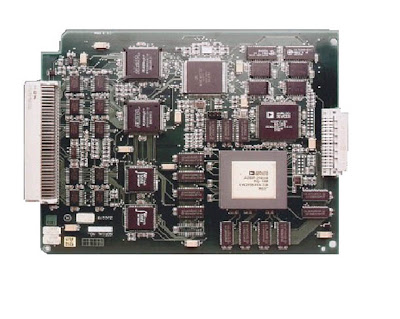
Circuit board of static relay

Introduction of static relays began in the early 1960’s. Their design is based on the use of analogue electronic devices instead of coils and magnets to create the relay
characteristic. Early versions used discrete devices such as transistors and diodes in conjunction with resistors, capacitors, inductors, etc., but advances in electronics enabled the use of linear and digital integrated circuits in later versions for signal processing and implementation of logic functions. While basic circuits may be common to a number of relays, the packaging was still essentially restricted to a single protection function per case, while complex functions required several cases of hardware suitably interconnected. User programming was restricted to the basic functions of adjustment of relay characteristic curves. They therefore can be viewed in simple terms as an analogue electronic replacement for electromechanical relays, with some additional flexibility in settings and some saving in space requirements. In some cases, relay burden is reduced,
making for reduced CT/VT output requirements.

Saturday, August 20, 2011

Relay Technology


The last thirty years have seen enormous changes in relay technology. The electromechanical relay in all of its different forms has been replaced successively by static, digital and numerical relays, each change bringing with it reductions and size and improvements in functionality.
At the same time, reliability levels have been maintained or even improved and availability significantly increased due to techniques not available with older relay types.
This represents a tremendous achievement for all those involved in relay design and manufacture.

1. ELECTROMECHANICAL  RE LAYS
These relays were the earliest forms of relay used for the protection of power systems, and they date back nearly 100 years. They work on the principle of a mechanical force causing operation of a relay contact in response to a stimulus. The mechanical force is generated through current flow in one or more windings on a magnetic core or cores, hence the term electromechanical relay. The principle advantage of such relays is that they provide galvanic isolation between the inputs and outputs in a simple, cheap and reliable form – therefore for simple on/off switching functions where the output contacts
have to carry substantial currents, they are still used. Electromechanical relays can be classified into several different types as follows:
a. attracted armature
b. moving coil
c. induction
d. thermal
e. motor operated
f. mechanical
However, only attracted armature types have significant  application at this time, all other types having been superseded by more modern equivalents.

2. Attracted Armature Relays

These generally consist of an iron-cored electromagnet that attracts a hinged armature when energised. A restoring force is provided by means of a spring or gravity so that the armature will return to its original position when the electromagnet is de-energised.
Typical forms of an attracted armature relay are shown in Figure 1. Movement of the armature causes contact

Wednesday, August 17, 2011

GROUNDING NEUTRAL POWER SYSTEM

In 1910, electric power systems are not grounded. This is due in the electric power systems is still small, so if there is fault current phase to ground fault current is still small, and usually less than 5 amperes. In general, if the fault current of 5 amperes or less, an electric arc that arise in contacts between the disturbed and the ground wire can still be extinguished itself. 

But the systems of power that increasingly large both in length and voltage. Thus the currents that arise in the event the greater the soil disturbance and electric arc that can no longer go out alone. Additional symptoms longer arc of land or ground arcing increasingly prominent. Symptoms of an arc of land is a process of termination (clearing) and at-re (restriking) from the electric arc repeatedly. This phenomenon is very dangerous because it may cause high transient overvoltages that can damage the equipment. 
System grounded in a state of disorder the ground wire


The methods of neutral earthing of the power systems are as follows:
1. Grounding through the resistance (resistance grounding).
2. Grounding through the reactor (reactor grounding).
3. Grounding without impedance (solid grounding).
4. Effective earthing (grounding effective).
5. With an impedance earthing reactors can be fickle (resonant grounding) or ground with Petersen coil.

In the systems are not grounded or delta system, the fault current depends on the capacitive impedance ZA, ZB and ZC, namely the capacitive impedance of each wire-phase to ground.

However, when the system is earthed fault current is no longer dependent only from impedance capacitive wires but also depends on the impedance earthing equipment and tansformator.

Unless the earth with Petersen coil, the impedance earthing device is very small compared to the capacitive impedance, or in other words it is no longer current noise depends on the impedance.

So with a grounded neutral fault current system clearly becomes larger than the current disruption in the delta system, but instead limit the voltage on the phases are not disrupted. So in determining the earthing impedance must be observed that the relationship between the large fault current and voltage that may arise.
System grounded in the disturbanceground wire


Working Principle Arrester

Protective equipment is the most complete arrester (lightning arresters; kada-sometimes also called a surge diverter). In essence this arrester consists of two elements: between fire (spark gap) and no linear prisoners or detainees valve (valve resistors), both connected in series

Upper and lower limits of the spark voltage is determined by the maximum system voltage and by the isolation level of protected equipment. Arresters actually consists of three elements: fire interrupted, prisoners or detainees faucet valves and system settings or voltage division (grading system).
As stated in advance, if the problem only protects the insulation against the danger of damage due to interference between the rod then just used that allows the spark when the voltage reaches a state of danger. In this case, the voltage alternating system will maintain the arc until the load breaker is opened. With the connect between this fire with a prisoner, then maybe the fire can be extinguished. But if the prisoner has a fixed price, then the voltage falls becomes greater, so the intention to abolish the voltage is less accomplished, and the purpose of protecting the insulation failed. Therefore use faucets prisoners, the which have specialproperties of the prisoner That minuscule voltage and largecurrent. Reduction process takes place once the prisonersQuickly During the overvoltage reaches its peakprice.Overvoltages in this case resulted in a drastic decline thanthe prisoners, so That the voltage current is limited despite the bigfall.


LA Voltage-Current Characteristics
If the maximum tension was more exhausted and live a normal voltage, current incarceration rose again so that the aftershocks are limited to approximately 50 A. Subsequent flow was finally turned off by the fire broke at the time The system voltage reaches the first zero point so that the tool acts as a valve that closes the flow; from here didapatkan name faucets prisoners. In the current arrester outages aftershocks large enough (200-300 A) is done with the help of a magnetic field. In this case, then both the amplitude and duration of follow-up current can be reduced and pemadamamannya system can be carried out before the voltage reaches zero price.

Aftershocks can be added that the current does not alwayshappen every time arresters work, depending on the presence or absence during overvoltage. This is understandable because the current apat aftershocks that just put out on the first zero currentor the previous one.
Based on its quality, known three arresters: substation (stationtype), the transmission line (line type) and distribution(distribution type) type substation kontruksinya heavier,karakteristinya better, higher current carrying capacity of its release (no more than 100 kA, 5 x 10 μs) and used to protect thesubstation and power transformers. This type of transmissionchannel is used to protect distribution transformers, transformer-powered small, and sometimes also a small substation. This type of distribution is primarily used to protect distribution transformers mounted on poles. Types trasnmisi and distributioncapacity are both made ​​to withstand 65 kA with 5 x 10 μs waveform.

In the normal voltage conditions, fire bulkhead prevents anycurrent flowing into the column. In the event of an overload, insulation fire will die and disposed of to ground pressure. 50 Hzcurrents that appear later are limited by the endurance blockvalve and the sparks that arise will be cooled at room sparks.Sparks will quickly extinguished and then be ready to protect thearrester equipment wire from the pressure of the next voltage.Blanking period is very short, rarely able to last more than afraction of a millisecond.


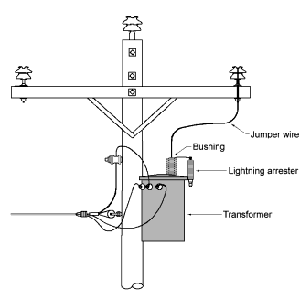
Arrester that allows us to reduce the BIL requirements of the devices installed at the substation. On HV and EHV systems, reducing the BIL will reduce the cost of the devices installed. picture below shows a lightning arrester installed at substation 150 kV and 500 kV.

Ligtning Arrester (LA)


The purpose of the arrester is to limit over-voltages that can appear on the transformer and other electrical devices either due to lightning or other electrical pressure. Base of the top of thearrester is connected to wires or terminals that must beprotected, and the base of the bottom connected to the ground.


Arrester insulation coordination is key in an electric powersystem. When the lightning came into the substation, arresterswork release electric charge (discharge), as well as reducing the voltage to be abnormal about the equipment in the substation.After a lightning arrester is released through, the current is stillflowing because of the system voltage; currents are calleddynamic or current flow aftershocks. Arresters must havesufficient resilience against the flow of energy from theseaftershocks, and should be able to decide, if at the time ofrelease arresters, voltage and current dynamic system is toohigh, then the arrester it may not be able to decide the flow ofaftershocks.


Requirements to be met by the arresters are as follows:1. Voltage spark (sparkover voltage) and the release voltage (discharge voltage), ie the voltage at the terminal at the time of the release should be quite low, so as to secure the insulating equipment. Spark voltage is also called the drain voltage between (gap breakdown voltage). Discharge voltage is also called residual stress (residual voltage) or IR voltage drop.2. Arresters should be able to decide the flow dynamics and can work continues as before. Limits of voltage current system in which the termination of these aftershocks are still possible, called the base voltage (rated voltage) of the arrester


Basic Impulse Level (BIL)

     How is the reaction of materials to the impulse voltageinsulation? An examination showed that the ability to withstandincreased when the voltage that flows take place in periods of very rapid. To illustrate, we will conduct testing on the transformerinsolasi, using 50 Hz sinusoidal voltage between the windings tothe tank. Along with increasing voltage, it will reach a point where the voltage will drop. We assume That point with 46 kV (RMS) or 65 kV peak.
     If now we use dc impulses between the windings to the ground, we find that it takes twice the peak voltage (or 130 kV) before isolation of the breakdown (broken). The same thinghappened on suspension insulators, bushings, etc., unless the ratio between the impulse voltage and ac voltage peak close to1.5.
     For standardization, and to facilitate comparisons betweenthe same tool in restraining impulses, standards organizationshave determined the shape and peak value of the impulse wave.
 Voltage Standard curve Impluls The equipment used todetermine the BIL
Picture above shows the standard impulse wave. The wavereached its peak after 1.2 μs and decreased to half of its peak at 50 μs. Peak voltage has a series of values ​​ranging from 30 kV to 2400 kV (see Table)
Voltage Peak To test BIL 1.2 x 50 Î¼s
Peak voltage is used to determine the quality of basicimpulse insulation (BIL) of a device. So, some devices(transformers, insulators, capacitors, resistors, bushings, etc.)that can withstand 1.2 x 50 μs waveform of 900 kV, is considered to have the quality of basic impulse insulation (BIL) of 900 kV.

Lightning antidote and Wire Transmission

Lightning antidote to the House

Lightning rod consists of a simple metal bars that are on higher ground than the building, which connects the lightning towards the ground electrode by means of the connecting wire. This tool is able to prevent high current passing through the building, which could result in fire, or endanger the occupants. Lightning can be very dangerous; when lightning release, this tool can create a very high voltage between the conductors to the ground.
Lightning rod that is more modern electrical devices used on the system. This tool will divert lightning and move the high-voltage current into the ground before damage to the electrical device.

Thunderstorms and Wire Transmission

When lightning directly on the wire transmission, which contain a large electrical currents, then there will be a voltage in a very large number of wire to the ground. Dielectric strength of air will overflow and pass flashover. Wire will heal by itself and the exc
ess voltage will disappear in less than 5 μs.
However, the sparks generated by the lightning current will produce a high ionization between the wires and the ground, which works like a short circuit. Consequently teagnagn normal alternating current will flow back and forth followed by a large ionized flow. Flows like this will not dampen the sparks until the circuit breaker to open at the bas
e end of the wire. Circuit breakers will flow fastest in 1 / 60 second, which is equivalent to 16,000 μs after lightning struck the wire.
Lightning strikes directly on the wire transmission is rare, most often, the lightning will grab the ground wire that protects the transmission wire. In the latter case, the local current is still flowing on the wire, which produces very high local stress. Concentrated flow will be divided into two waves moving in opposite directions near the speed of light (300 m / μs). High voltage is an impulse wave that emerged from point to another, between the wire and ground Peak voltage (refer to the crest of a wave) can force one / two million volts. Ab gathered in front of the wave range of 300 m, while the tail bc several kilometers.
Waves that represent the point value per point of the current flowing in the wire. Most wire air, the ratio between surge voltage and surge current equivalent of about 400 Ω resistance. Voltage of 800,000 volts of pressure at some point will be followed by the current pressure on the 800.000/400 = 2,000 A.

During the wave goes through the wire, and I2R losses in the corona gradually come down, and followed by a drop in peak voltage.

When the wave reaches the insulator, the insulator will experience a large excess voltage. This period of rest is the voltage equivalent to the time it took the wave to reach the insulator. Voltage rises from its nominal value to hundreds of kilo-volt in 1 μs, corresponding to the wavelength of the front ab. If the insulator is not able to withstand the excess voltage, the flashover occurs, and generate currents that drive next-breaker will cause the circuit to work. On the other hand, if the insulation resistance, the wave will continue to run along the wire until it finally reached the substation. And this wave of impulse will result in damage.
Winding transformers, condensers, reactors and others, will be severely damaged if the experience flashover to ground. The cost of expensive repairs and even total destruction would make such a device can not function anymore. Excess stress can cause damage to the circuit breakers, separators, insulators, relay and others, which is a substation devices. To reduce the impulse voltage on the substation, lighting arresters (LA) is installed on all the wires that go into substation.

LA is designed to prevent the peak voltage that exceeds a certain level, such as 150 kV. Instead, the device in the substation is designed to resist the impulse voltage is higher than the lightning rod, such as 650 kV. Thus, if the voltage of 1000 kV substations into, LA it will divert most of the energy that comes into the ground. Residual impulse wave passing through LA would have the strength of 150 kV. The device is designed substation 650 kV impulse withstand.

lightning and electrical energy


Clap


During the rainy season, through a fairly complicated process, charge separation occurs within a cloud, so that the positive charges move to the top of the cloud while negative charge stays below

Such transfer will cause an electric field inside the cloud. In addition, the negative charge at the base of the clouds refused to free electrons that exist underneath. As a result, the T becomes positively charged, due to induction. It will be formed an electric field and other potential between the cloud base and earth. So, appears an electric field between the electrons are repelled from the region T, with a positive charge at the top of the cloud.


The more positive charge that moves upward, the electric field under a cloud becomes stronger. This goes on until it reaches a critical level of ionization of air which begin to break down.Ionization occurs as the first time on the top roof of a building or tree tops, and sometimes appear as bluish light.


When the electric field is strong enough, lightning will immediately grabbed from cloud to earth. A lightning strike consists of a charge transfer from 0.2 to 20 coulombs, with the potential / voltage differential reaches hundreds of millions of volts. The speed of each stroke peaked around one or two microseconds and then drops by half within 40 μs. What is usually seen as a lightning strike, actually consists of several strike that followed each other in a very rapid timeframe. Total time release can last for 200 ms. The release also occurred between the positive with a negative flow in the cloud, rather than between the cloud base and ground. Thunder sounds generated supersonic wave riding. Lightning is caused by expansion of air around the lightning seized.

understanding electricity

Electricity is the nature of the objects that emerge from the existence of electric charge. Electricity, can also be interpreted as follows:
- Electricity is the condition of certain subatomic particles, likeelectrons and protons, which led to the withdrawal and rejection ofstyles in between.

- Electricity is a source of energy that is channeled through wires.Electrical currents arising from electric charge flowing frompositive to negative channel channel.


Together with magnetism, electricity form the fundamentalinteraction known as electromagnetism. Electricity allows the occurrence of many well-known physical phenomena, such aslightning, electric fields and electric currents. Electricity use is common in industrial applications such as electronics and electric power.
Related Posts Plugin for WordPress, Blogger...